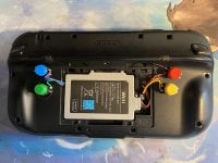
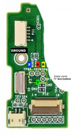
I have back buttons - A&B on the left and X&Y on the right side. I have tapped into the test points that sudomod's evertith labelled as being for the d-pad directions. I did some probing with my multimeter and some aluminium foil to bridge the socket pins and didn't find any points with continuity to the d-pad/L/ZL ribbon cable that weren't just ground (can't upload my Excel file, which is 8.5 MB in size due to my including photos of clusters of test points to help me not get lost). I don't really want to try soldering to the ribbon cable or its 0.5 mm pin pitch socket on the board. Any ideas?


Stage 2 of the upgrade is adding slightly bigger rumble motors than the single button-sized motor. Looking at the empty space in the grips, I considered a '140' model motor, but it would be too long and I would need to cut away some of the internal struts, which could then lead to the weights hitting and tearing the flexible PCBs the face & shoulder buttons are on. I mocked this up with card rolled into a tube of the right diameter. The largest cylinder I could jam in is about 25 mm in both length and diameter. So I settled on 'm20' motors - 15 mm long by 10 wide by 8 deep, with the weight extending 7 mm out the end. They're rated for '1.5/3/6' V so should be safe to run from the 3.7 V battery the gamepad uses, and seem powerful enough on the 3V my 2xAA test battery pack puts out.
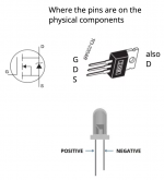
I mocked up the circuit I am going to use - I suspected that I shouldn't be connecting the motors directly to the original control pins, as I'm planning to use ones that are significantly larger than the original. The component for controlling a higher-current device from a smaller signal is a MOSFET. Fortunately for me, this is the same problem amateur roboticists have in running a motor from an Arduino. I identified IRLZ44N as the relevant model. Amazon's search is not very helpful, and I failed to spot that the parts I ordered were IRFZ44N. That is no good as I need a logic-level MOSFET - the regular type need a gate signal of around 10V. I tried to return them, but it seems that would cost them more than just refunding me, so I got to keep them. I now have IRLZ34Ns - the '34' vs '44' is about the maximum current it can supply - 30 A is still much more than my rumble motors will draw.

I drew out and mocked up the circuit outside the GamePad with croc-clip leads. I tried out a 2.2 MΩ 'pull-down' for draining the charge off the MOSFET when the signal is switched off. Otherwise it would stay on once it got triggered the first time. This value is a compromise between draining slowly and the current that will constantly flow even when nothing is happening - I went for minimum stand-by power consumption. I tried a 220 Ω gate resistor to limit the current drawn to switch the MOSFET on - the whole point of the extra components was to avoid the risk of frying the circuit board by drawing a large current from the rumble motor pins. Again it's a compromise, but in this case too large a value would also be dangerous, as the transistor will get hot if it spends too much time switching between the off and on states. I probably don't need to worry about this too much - it's more of a problem with circuits that switch on and off repeatedly when in use e.g. PWM control for motor speed or LED brightness.
Another way a MOSFET can get toasted in this circuit is the voltage spike you get when turning a motor off (coils of wire like motor windings are inductors and resist rapid changes in current, generating a large voltage to try to keep the current going). The standard way of dealing with this is having a 'flyback diode' wired up 'backwards' so the loop of circuit with the motor can avoid overloading the MOSFET. I don't have any regular diodes, but I do have some white LEDs. In general this is a terrible idea, but I think I can get away with it in this fairly low-powered circuit. White LEDs need 3-5 V to work, and seem to be able to survive 5 V in reverse bias. This is more than the forward voltage of the battery, so that's OK. I have quite a few of them, so I can sacrifice one to experiment with. It turns out that the voltages involved in my test circuit don't even seem to be enough to light the LED properly - it glows a dim yellow both steadily in the forward direction with a 22 Ω series resistor as a model for the OG rumble motor, and when it flashes when the motor switches off. This is maybe not totally realistic, as the GamePad's battery is 3.7 V not 3.0, but the spike I was worried about was from the motor, and the rate of change of current will be limited by the MOSFET not the supply voltage, so if I haven't fried the flyback LED in my test I should be OK.


At this point I opened up the GamePad again to refresh my memory of what the OG rumble motor voltage actually was. I was expecting the black wire to be 'common ground' and the red wire to be ground too when the rumble is off, and a few volts when it's on. To my surprise, the red wire is always at 2.8 V relative to the board's ground. The motor gets turned on when the black wire changes from +2.8 V to 0 V. This seems like it would throw off my circuit design, as the gate signal is supposed to be compared to the same ground potential as the output's ground. Having the transistor on the 'high' side is supposed to use a p-type not an n-type MOSFET. I played around with the circuit on paper and then with my croc clips, and I think it should be OK. The MOSFET only needs to have a potential difference between the gate and source/ground, so it shouldn't care if the no-signal condition is because both pins are at 2.8 V. And in this state the path from the motor/drain pin to the source / supposed ground isn't conducting, so the motor won't care that it's at 2.8 V. When the source pin is switched to ground and the path from my new rumble motor starts conducting, the source pin will be grounded as expected.


I intend to have two motors in one side and one in the other, even though they will be controlled by a single signal, unlike the Xbox / PS controllers' independent signals for stronger rumble on the left. To avoid the possibility that the doubled motors' weights end up on opposite sides of the spindle and thus the wobbling effect cancels, I will connect them so they spin in opposite directions so there will be wobbling on some axis.

Unfortunately my circuit didn't work when plugged into the GamePad - the voltage across the original motor, and therefore between my gate and source, reduced to ~2 V, which is around the threshold voltage (at which the MOSFET starts conducting only a very small current). I'm not awfully surprised - the whole point of adding extra components rather than just replacing / putting my bigger motors in parallel with the original was to avoid drawing a large current from pins that might not be designed for it. I daisy-chained three MOSFETS, with each drain connecting to the next gate with a 220 ohm resistor, and connected to the battery with a 2.2 megaohm resistor. I needed three, because the second one gives an inverted output. My soldering to the motors wasn't great, and I need to work on mounting the motors securely and routing all the cables so the case will close. I'm giving up on having the MOSFETS inside, and if I can't get them to stay in place inside the GamePad, I will gut the Uboost battery pack (the batteries of which don't hold a charge now - It's there as a kickstand and because I can't locate the original battery door) and house them in there. This would also have the advantage of being outside the case, so I can get at them more easily. I'm getting fed up with unscrewing the tri-wing screws, even though I have added 'dupont wire' connectors so I can unplug everything when I take the back off.


Stage 2 of the upgrade is adding slightly bigger rumble motors than the single button-sized motor. Looking at the empty space in the grips, I considered a '140' model motor, but it would be too long and I would need to cut away some of the internal struts, which could then lead to the weights hitting and tearing the flexible PCBs the face & shoulder buttons are on. I mocked this up with card rolled into a tube of the right diameter. The largest cylinder I could jam in is about 25 mm in both length and diameter. So I settled on 'm20' motors - 15 mm long by 10 wide by 8 deep, with the weight extending 7 mm out the end. They're rated for '1.5/3/6' V so should be safe to run from the 3.7 V battery the gamepad uses, and seem powerful enough on the 3V my 2xAA test battery pack puts out.
I mocked up the circuit I am going to use - I suspected that I shouldn't be connecting the motors directly to the original control pins, as I'm planning to use ones that are significantly larger than the original. The component for controlling a higher-current device from a smaller signal is a MOSFET. Fortunately for me, this is the same problem amateur roboticists have in running a motor from an Arduino. I identified IRLZ44N as the relevant model. Amazon's search is not very helpful, and I failed to spot that the parts I ordered were IRFZ44N. That is no good as I need a logic-level MOSFET - the regular type need a gate signal of around 10V. I tried to return them, but it seems that would cost them more than just refunding me, so I got to keep them. I now have IRLZ34Ns - the '34' vs '44' is about the maximum current it can supply - 30 A is still much more than my rumble motors will draw.

I drew out and mocked up the circuit outside the GamePad with croc-clip leads. I tried out a 2.2 MΩ 'pull-down' for draining the charge off the MOSFET when the signal is switched off. Otherwise it would stay on once it got triggered the first time. This value is a compromise between draining slowly and the current that will constantly flow even when nothing is happening - I went for minimum stand-by power consumption. I tried a 220 Ω gate resistor to limit the current drawn to switch the MOSFET on - the whole point of the extra components was to avoid the risk of frying the circuit board by drawing a large current from the rumble motor pins. Again it's a compromise, but in this case too large a value would also be dangerous, as the transistor will get hot if it spends too much time switching between the off and on states. I probably don't need to worry about this too much - it's more of a problem with circuits that switch on and off repeatedly when in use e.g. PWM control for motor speed or LED brightness.
Another way a MOSFET can get toasted in this circuit is the voltage spike you get when turning a motor off (coils of wire like motor windings are inductors and resist rapid changes in current, generating a large voltage to try to keep the current going). The standard way of dealing with this is having a 'flyback diode' wired up 'backwards' so the loop of circuit with the motor can avoid overloading the MOSFET. I don't have any regular diodes, but I do have some white LEDs. In general this is a terrible idea, but I think I can get away with it in this fairly low-powered circuit. White LEDs need 3-5 V to work, and seem to be able to survive 5 V in reverse bias. This is more than the forward voltage of the battery, so that's OK. I have quite a few of them, so I can sacrifice one to experiment with. It turns out that the voltages involved in my test circuit don't even seem to be enough to light the LED properly - it glows a dim yellow both steadily in the forward direction with a 22 Ω series resistor as a model for the OG rumble motor, and when it flashes when the motor switches off. This is maybe not totally realistic, as the GamePad's battery is 3.7 V not 3.0, but the spike I was worried about was from the motor, and the rate of change of current will be limited by the MOSFET not the supply voltage, so if I haven't fried the flyback LED in my test I should be OK.
At this point I opened up the GamePad again to refresh my memory of what the OG rumble motor voltage actually was. I was expecting the black wire to be 'common ground' and the red wire to be ground too when the rumble is off, and a few volts when it's on. To my surprise, the red wire is always at 2.8 V relative to the board's ground. The motor gets turned on when the black wire changes from +2.8 V to 0 V. This seems like it would throw off my circuit design, as the gate signal is supposed to be compared to the same ground potential as the output's ground. Having the transistor on the 'high' side is supposed to use a p-type not an n-type MOSFET. I played around with the circuit on paper and then with my croc clips, and I think it should be OK. The MOSFET only needs to have a potential difference between the gate and source/ground, so it shouldn't care if the no-signal condition is because both pins are at 2.8 V. And in this state the path from the motor/drain pin to the source / supposed ground isn't conducting, so the motor won't care that it's at 2.8 V. When the source pin is switched to ground and the path from my new rumble motor starts conducting, the source pin will be grounded as expected.
I intend to have two motors in one side and one in the other, even though they will be controlled by a single signal, unlike the Xbox / PS controllers' independent signals for stronger rumble on the left. To avoid the possibility that the doubled motors' weights end up on opposite sides of the spindle and thus the wobbling effect cancels, I will connect them so they spin in opposite directions so there will be wobbling on some axis.
Unfortunately my circuit didn't work when plugged into the GamePad - the voltage across the original motor, and therefore between my gate and source, reduced to ~2 V, which is around the threshold voltage (at which the MOSFET starts conducting only a very small current). I'm not awfully surprised - the whole point of adding extra components rather than just replacing / putting my bigger motors in parallel with the original was to avoid drawing a large current from pins that might not be designed for it. I daisy-chained three MOSFETS, with each drain connecting to the next gate with a 220 ohm resistor, and connected to the battery with a 2.2 megaohm resistor. I needed three, because the second one gives an inverted output. My soldering to the motors wasn't great, and I need to work on mounting the motors securely and routing all the cables so the case will close. I'm giving up on having the MOSFETS inside, and if I can't get them to stay in place inside the GamePad, I will gut the Uboost battery pack (the batteries of which don't hold a charge now - It's there as a kickstand and because I can't locate the original battery door) and house them in there. This would also have the advantage of being outside the case, so I can get at them more easily. I'm getting fed up with unscrewing the tri-wing screws, even though I have added 'dupont wire' connectors so I can unplug everything when I take the back off.