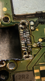
This board came from someone tried but failed to swap the type C port. Instead, he ripped off some soldering pads on the board.
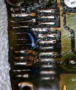
As seen in attached photo "TypeC_Trace", result of me trying to repair the broken trace by both jump wires(too thin?) and repairing pads(too thin in another way?).
Both methods failed.
Jump wire failed with good connection (tested with the pinout board in continuity test), but even RCM couldn't be detected by computer on the port.
Repairing pad failed with no connection of some pins from port to the board, meaning that some pins just not soldered.
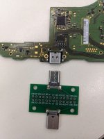
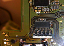
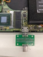
Now I'm thinking about using the pinout board with thicker jump wires to solder the pins on the Switch board directly as shown in "TypeC_Pins". Then reassemble the console with the "TypeC_Propose" layout, which has the jump wires go through the top of RAM to connect the Switch board to the pinout board. The pinout board will be hanging outside as an extended port. But the bulky "port" for me is just fine because I expect to use this console for TV mode only with a customized container if the pinout board must exist.
PS. the pins were labeled by a good reference board with the same pinout board with same orientation. They're correct. double checked.
My questions are:
1: Is my proposal with long jump wires feasible? Will this affect the console's performance?
2: Should / Can the pinout board be replaced by something less bulky?
3: Or should I try to solder the port normally? I doubt this because the board had been tortured by the original owner(multiple broken components, which I fixed already) and me(reheating the port area multiple times for the port's soldering). Reheating again might cause issue in the PCB, I worry.
As seen in attached photo "TypeC_Trace", result of me trying to repair the broken trace by both jump wires(too thin?) and repairing pads(too thin in another way?).
Both methods failed.
Jump wire failed with good connection (tested with the pinout board in continuity test), but even RCM couldn't be detected by computer on the port.
Repairing pad failed with no connection of some pins from port to the board, meaning that some pins just not soldered.
Now I'm thinking about using the pinout board with thicker jump wires to solder the pins on the Switch board directly as shown in "TypeC_Pins". Then reassemble the console with the "TypeC_Propose" layout, which has the jump wires go through the top of RAM to connect the Switch board to the pinout board. The pinout board will be hanging outside as an extended port. But the bulky "port" for me is just fine because I expect to use this console for TV mode only with a customized container if the pinout board must exist.
PS. the pins were labeled by a good reference board with the same pinout board with same orientation. They're correct. double checked.
My questions are:
1: Is my proposal with long jump wires feasible? Will this affect the console's performance?
2: Should / Can the pinout board be replaced by something less bulky?
3: Or should I try to solder the port normally? I doubt this because the board had been tortured by the original owner(multiple broken components, which I fixed already) and me(reheating the port area multiple times for the port's soldering). Reheating again might cause issue in the PCB, I worry.