Hello
After reading quite a lot and watching videos on youtube, i decided to install a chip in my Nintendo Switch Lite to jailbreak it.
There seem to be quite a lot of different chips out there.
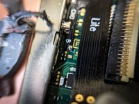
This is the one I have.

One of the problems i have is I don't know what this chip is called. People seem to mix the names a lot.
Is it a RP2040? Is it a Picofly? Is it a HWFly? No clue at the moment....
I have put picofly firmware on it version 2.7.3 (Ansem-SoD/Picofly/tree/main/Firmwares on Github)
After soldering, i tried to turn on the console. The console boots in the official nintendo firmware. The error code on the chip is 2 short flashed.
(** RST is not connected)
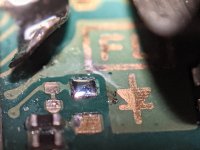
So i guess i have somewhere a bad soldered point.
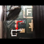
Can someone point me to the mapping of the letters? I have to solder A, B, C, D and 3,3V on one of the cables.
How do those points map to RST, CMD, D0 and CLK?
I would also like to know how i can measure if the different points are correctly soldered.
Do i need to measure the voltage levels on each point when the battery of the switch is connected? What should be the values?
Thank you very much already for your time.
After reading quite a lot and watching videos on youtube, i decided to install a chip in my Nintendo Switch Lite to jailbreak it.
There seem to be quite a lot of different chips out there.
This is the one I have.
One of the problems i have is I don't know what this chip is called. People seem to mix the names a lot.
Is it a RP2040? Is it a Picofly? Is it a HWFly? No clue at the moment....
I have put picofly firmware on it version 2.7.3 (Ansem-SoD/Picofly/tree/main/Firmwares on Github)
After soldering, i tried to turn on the console. The console boots in the official nintendo firmware. The error code on the chip is 2 short flashed.
(** RST is not connected)
So i guess i have somewhere a bad soldered point.
Can someone point me to the mapping of the letters? I have to solder A, B, C, D and 3,3V on one of the cables.
How do those points map to RST, CMD, D0 and CLK?
I would also like to know how i can measure if the different points are correctly soldered.
Do i need to measure the voltage levels on each point when the battery of the switch is connected? What should be the values?
Thank you very much already for your time.