Wii U Stuck on Logo

ChefVortivask

Well-Known Member
OP
Member
Joined
Apr 3, 2023
Messages
340
Trophies
0
Age
26
XP
567
Country
United States
Hello everyone,

First time poster here. I decided to make this post since I am having issues with my Wii U. Currently, my Wii U will not boot up to the main menu. It stays stuck on the Wii U logo indefinitely.

There are a few things to note about my console. The console is the black 32 gb model. I believe it was bought during the 2012 holiday season (release) as we were expecting to play Pikmin 3 before it got delayed. The system has never been modded in any fashion. It was not the most heavily played console, and I can't even give a good estimate of when it was last used (at least more than 3 years).

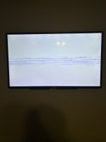
I have already tried doing the UDPIH, however it does not seem to be working. When using the second recovery menu, I get a white screen with some blue lines (see attached image). I believe this is similar to what @fadafwet described in his post. I was able to get the logs from the system, which I have attached to this post. Any idea what the issue may be and how to fix it? Any help would be much appreciated.
 

Attachments

  • Garbled Screen.jpg
    Garbled Screen.jpg
    1.5 MB · Views: 97
  • logs.zip
    63.9 KB · Views: 88

ChefVortivask

Well-Known Member
OP
Member
Joined
Apr 3, 2023
Messages
340
Trophies
0
Age
26
XP
567
Country
United States
I intend to finish up the repair later today. I have a few other things I need to do first. In the meantime, I did want to clarify a few things.

From what I understand, the CLK trace is cut when we want to disable the eMMC as well as when we want to dump it. If the eMMC were fine, we'd just reestablish the connection (either through a jumper or a solder blob), but in the case of a defective eMMC, we then need to ground it. With the NAND-AID, closing the DIS jumper grounds the CLK connection. Is that correct? I'm not at all in expert in electronics, but I do want to have at least a little understanding about what is going on. I also don't want to mess up the installation. Right now I need to cut the CLK trace and then I believe I need to close the DIS jumper.
 

V10lator

Well-Known Member
Member
Joined
Apr 21, 2019
Messages
2,664
Trophies
1
Age
36
XP
5,634
Country
Germany
@ChefVortivask Your assumtion seems correct to me.

You cut the CLK trace and then connect both ends to NAND-AID. The side facing to the SBC will be connected to the SD cards CLK and the one on the eMMC will be floating now. So you need to ground that floating line to make sure the eMMC is disabled (floating is an undefined state), that's what the DISable pads are for.

In case you don't cut CLK, don't shortcut the DIS pads and don't enter an SD card into NAND-AID you can use NAND-AID to hardware dump the eMMC chip (I would love some jumpers here cause most people will want to replace the eMMC after dumping it but cutting the CLK trace after soldering the NAND-AID in sounds pretty hard to do... But Voultar didn't want to add jumpers for whatever reasons).
 

SDIO

Well-Known Member
Member
Joined
Feb 13, 2023
Messages
2,336
Trophies
0
Age
28
XP
1,475
Country
Germany
No for dumping you need to cut the clock trace, or else the Wii U will drive it's clock and will fight the clk of the card reader. The clk pad on the NAND aid is connected to the eMMC side and the SD slot is connected to the Wii U side.
The NAND-AID is designed for the following workflow: cut the clk trace, solder the NAND-AID. Dump the eMMC using a SD card reader connected to the pads of the NAND AID. Then writing the image to an SD card using the Cardreader. Then you would close the dis jumper and insert the sdcard in the NAND AID. No Jumper needed.

@ChefVortivask already has the dump, so that part is irrelevant, but he still needs to stop the eMMC from interfering. That can be done by either cutting the clk trace, because without a clk the eMMC won't do anything or he can remove the resistors, so the eMMC is disconnected from the signals on the board and therefore can't mess with them, even if it still gets a clk.

cutting the trace is permanently modifying the board and you also have to be careful to don't cut other traces. So some people might prefer removing the resistors. But cutting the trace gives more flexibility
 

ChefVortivask

Well-Known Member
OP
Member
Joined
Apr 3, 2023
Messages
340
Trophies
0
Age
26
XP
567
Country
United States
No for dumping you need to cut the clock trace, or else the Wii U will drive it's clock and will fight the clk of the card reader. The clk pad on the NAND aid is connected to the eMMC side and the SD slot is connected to the Wii U side.
The NAND-AID is designed for the following workflow: cut the clk trace, solder the NAND-AID. Dump the eMMC using a SD card reader connected to the pads of the NAND AID. Then writing the image to an SD card using the Cardreader. Then you would close the dis jumper and insert the sdcard in the NAND AID. No Jumper needed.

@ChefVortivask already has the dump, so that part is irrelevant, but he still needs to stop the eMMC from interfering. That can be done by either cutting the clk trace, because without a clk the eMMC won't do anything or he can remove the resistors, so the eMMC is disconnected from the signals on the board and therefore can't mess with them, even if it still gets a clk.

cutting the trace is permanently modifying the board and you also have to be careful to don't cut other traces. So some people might prefer removing the resistors. But cutting the trace gives more flexibility
Thank you for the explanation. I personally don't see how cutting the trace is that difficult, even if the NAND-AID were installed. In your opinion, would you prefer cutting the CLK trace or removing those resistors? I have a hot air station (which is what I used to remove the extra capacitor I had in the way) so I think I can remove those resistors fairly easily, but since you are a sort of pioneer in this mod, I'd like to know if you have a preference.
 

ChefVortivask

Well-Known Member
OP
Member
Joined
Apr 3, 2023
Messages
340
Trophies
0
Age
26
XP
567
Country
United States
Yeah I don't see me having the eMMC replaced if the SD card works just as fine. I'll make the small cut. My only concern with removing the resistors with hot air is the possibility of blowing away the neighboring resistors.
 

ChefVortivask

Well-Known Member
OP
Member
Joined
Apr 3, 2023
Messages
340
Trophies
0
Age
26
XP
567
Country
United States
Would it have to be all the data resistors (DAT 0, 1, 2, and 3) as well as CMD, or just one of the DAT resistors? I assume all of them since it would be odd to have part of the data coming in.
 

ChefVortivask

Well-Known Member
OP
Member
Joined
Apr 3, 2023
Messages
340
Trophies
0
Age
26
XP
567
Country
United States
Yeah I'm thinking I'll just cut the CLK trace. Removing the resistors isn't necessarily hard, but it would be some work to reinstall them if I ever wished to. Normally I'm against hard modifications of hardware (in this case cutting the CLK trace), but it seems so easy to just bridge the two pads as opposed to reinstalling all 5 resistors.
 

ChefVortivask

Well-Known Member
OP
Member
Joined
Apr 3, 2023
Messages
340
Trophies
0
Age
26
XP
567
Country
United States
I'm having a very difficult time soldering the ground connection from the NAND-AID to the board. I know @Voultar said this is the easiest part to solder, but I hope that's not true. I simply can't make good contact to the Wii U ground pad through the NAND-AID, and as @SDIO said, this pad seems to just suck up the heat like a sponge. I'm going to try the technique of preheating the board using a hot air station, but I would like to know what kinds of iron tips people are using for this. I have a Hakko FX888D and just received a new tip for it today. It's a chisel tip that just barely makes it through the NAND-AID. I've done a bit of soldering before. I've made an Ashida Wii portable so I'd like to think I can do soldering fairly well. Does anyone have any advice on how to do this?
 

Ysecond

Well-Known Member
Member
Joined
Apr 27, 2023
Messages
186
Trophies
0
Age
26
XP
479
Country
China
I'm having a very difficult time soldering the ground connection from the NAND-AID to the board. I know @Voultar said this is the easiest part to solder, but I hope that's not true. I simply can't make good contact to the Wii U ground pad through the NAND-AID, and as @SDIO said, this pad seems to just suck up the heat like a sponge. I'm going to try the technique of preheating the board using a hot air station, but I would like to know what kinds of iron tips people are using for this. I have a Hakko FX888D and just received a new tip for it today. It's a chisel tip that just barely makes it through the NAND-AID. I've done a bit of soldering before. I've made an Ashida Wii portable so I'd like to think I can do soldering fairly well. Does anyone have any advice on how to do this?
Yeah,I'm soldering two wiius with NAND-AID. Soldering the ground is very difficulty ,I use both Soldering pen and Hot Air Station :D ,But it's not very beautiful either,Unless I buy a high-power soldering pen(maybe 80W?)?
Don't mind, as long as it works properly.:rofl2:
 

SDIO

Well-Known Member
Member
Joined
Feb 13, 2023
Messages
2,336
Trophies
0
Age
28
XP
1,475
Country
Germany
I used a tip which was flat at the tip and was small enough to reach through to the pad and cranked the temp up to the max (450C). Additionally I used a little bit of hot air to heat the area. Also I used leaded solder and cleaned the pad before with leaded solder.
Also that was the first connection I soldered, so I could test it for strength without stressing the other pads.
It still took a good time till it properly flowed and I had to add flux a few times.

Also make sure the clock trace is still cut after the soldering is done. I had to retrace the cut with the knife as it seems it soldered back together in the cut (there was no visible bridge)
 

ChefVortivask

Well-Known Member
OP
Member
Joined
Apr 3, 2023
Messages
340
Trophies
0
Age
26
XP
567
Country
United States
I used a tip which was flat at the tip and was small enough to reach through to the pad and cranked the temp up to the max (450C). Additionally I used a little bit of hot air to heat the area. Also I used leaded solder and cleaned the pad before with leaded solder.
Also that was the first connection I soldered, so I could test it for strength without stressing the other pads.
It still took a good time till it properly flowed and I had to add flux a few times.

Also make sure the clock trace is still cut after the soldering is done. I had to retrace the cut with the knife as it seems it soldered back together in the cut (there was no visible bridge)
I actually have my iron a little bit hotter than that. Interestingly enough I used to use my iron at a far lower temperature and it worked just fine with the solder I use. I'm not entirely sure what the issue is since the tips are clean. Perhaps it's a problem with the iron? I'm going to look into it, but do you have a picture of the tip you use so I can get an idea of if I have what I need?
 

SDIO

Well-Known Member
Member
Joined
Feb 13, 2023
Messages
2,336
Trophies
0
Age
28
XP
1,475
Country
Germany
The problem is, that the massive ground plane is just sucking the heat away. Copper is a good heat conductor and also has some heat capacity. The groundplane first needs to be 'saturated' with enough heat, so either give it more time or preheat it with hot air. Also make sure you use enough flux.
What Power can your Iron output?

The tips I used looked like this: https://www.sra-shops.com/pub/media/docs/srasolder/datasheet/tds-aotbevelset.pdf I used two different sizes
 

ChefVortivask

Well-Known Member
OP
Member
Joined
Apr 3, 2023
Messages
340
Trophies
0
Age
26
XP
567
Country
United States
Yeah I speculated that the ground plane is probably fairly big and since copper is a great conductor of heat, it takes a lot to heat up a specific location to a high enough temperature. According to the manual, the station itself 70 W while the actual iron is 65 W. I'm going to do a temperature adjustment when I get home since I'm really starting to think there is a disconnect between the temperature reading of the station and the actual temperature of the iron, therefore I may not have the tip hot enough to do this joint effectively.

As for that tip shape, I had considered using a shape like that. The last tip I tried was a chisel tip. Once I do the temperature adjustment, I'll try that tip again to see if I can do it. Otherwise I'll purchase tips with the shape that you used.
 

SDIO

Well-Known Member
Member
Joined
Feb 13, 2023
Messages
2,336
Trophies
0
Age
28
XP
1,475
Country
Germany
70W should be enough. Just try giving it more time and add a little bit of flux from time to time. If you have hot air use that to help, but take care to not desolder anything. If you don't have hot air, maybe use a hair dryer to heat up the board as much as possible, before you to to solder it.

But I really like that tip, as it also can remove a bit of solder or drag it, which is nice for going over an array of connections like on the sd slot
 

Site & Scene News

Popular threads in this forum

General chit-chat
Help Users
    Psionic Roshambo @ Psionic Roshambo: It will be fine