Just to add with the mosfet, make sure to use awg34 or 32 (thicker wire) for the drain. I use 34awg and works everytime. I had issues with 36 or 40awg for drain based on my experience.
You are using an out of date browser. It may not display this or other websites correctly.
You should upgrade or use an alternative browser.
You should upgrade or use an alternative browser.
Staff Posts
Recent threadmarks
sharing files
Important Posts
Recent threadmarks
Firmwares
And yes, it is working good with instant glitch.Just follow the image above and you will be good. Dont forget to isolate with kapton tape in the end.
Well, I switched to the front and still ==*.
Just to add with the mosfet, make sure to use awg34 or 32 (thicker wire) for the drain.
...but I will try switching the wire to a larger gauge before complaining too much
")
All points make correct continuity, this photo was taken after I reopened so I haven't tidied the thermal paste.
Well, I switched to the front and still ==*.
few things.
1. the chip is busted, try to check the resistor at d0/clk/cmd line.
2. the mosfet is bad, i had a bunch of IRH mosfets (50+) of them are bad. I just switch from aon6414a and never had this issue.

Switch works without that cap. You can also replace that cap with ones found on rp2040 board.Well, while trying to change the wires I broke the CPU cap. I guess that ends this adventure! Thanks again for all your help friends, appreciate it!
Don't give up, remove everything, clean everything, start over.
Seems that you need better tools or skills (or both).
Use 0.1-0.5 solder tip, use led based solder wire, good flux. Use 350°-400° temperature for short period of time (don't overheat the components or the board). For Source connection use apu shield instead of the square point on the apu itself.
Try to avoid using magnet (enameled) wire, if you don't have experience with it you might end up with cold joint or a short somewhere, use 36-40awg pfa or ptfe or silicone wire.
Good luck

I think I'll put in an order with digikey and use the shipping time to cool my heels.Switch works without that cap. You can also replace that cap with ones found on rp2040 board.
Don't give up, remove everything, clean everything, start over.
Seems that you need better tools or skills (or both).
Use 0.1-0.5 solder tip, use led based solder wire, good flux. Use 350°-400° temperature for short period of time (don't overheat the components or the board). For Source connection use apu shield instead of the square point on the apu itself.
Try to avoid using magnet (enameled) wire, if you don't have experience with it you might end up with cold joint or a short somewhere, use 36-40awg pfa or ptfe or silicone wire.
Good luck
There is definitely a skill issue, but I want to learn and this particular switch was already in rough cosmetic shape so it's as good a test bed as anything.
Tools are a cobbled together set that I'm upgrading as I go, but I think I'm mostly limited by ability.
Stripping the cap was a mishandled tweezer trying to bend the wire already soldered to the cap. I thought I had it pinned with one set, but it wasn't actually pinched. Doh!
Yes, a couple of times. Works greatwho installed picofly to unpatched v1 before? worked?

I spent two hours yesterday on a console.
Error ==*
I tested different mosfets.
In the end the error came from the fact that I was using a chip that was already used on another console.
By changing the chip, it starts perfectly.
Error ==*
I tested different mosfets.
In the end the error came from the fact that I was using a chip that was already used on another console.
By changing the chip, it starts perfectly.

I spent two hours yesterday on a console.
Error ==*
I tested different mosfets.
In the end the error came from the fact that I was using a chip that was already used on another console.
By changing the chip, it starts perfectly.
you can force reset the chip by connecting pin0 to gnd on power-on. might have saved you the swap
Hi do you have a photo of your installation with this mosfet?few things.
1. the chip is busted, try to check the resistor at d0/clk/cmd line.
2. the mosfet is bad, i had a bunch of IRH mosfets (50+) of them are bad. I just switch from aon6414a and never had this issue.
View attachment 421467
you can force reset the chip by connecting pin0 to gnd on power-on. might have saved you the swap
What's the pin0 equivalent on the SEEED Xiao? The labeled 0 is tied to the RST pins as far as I can tell.

Here are some examples of the installation I did today on a customer's OLED switch.
I always follow the same basic electronics principles in a fusion of knowledge acquired in this forum on the best tips for a successful installation.Said that, lets begin :
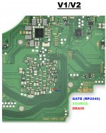
I always start by removing the metal protection from the CPU with a needle tip and being very careful not to damage any of the components around the metal fittings. Then glue the mosfet aligned with the soldering points (Source and Drain)

I always start by removing the metal protection from the CPU with a needle tip and being very careful not to damage any of the components around the metal fittings. Then glue the mosfet aligned with the soldering points (Source and Drain)

I keep the wire that connects the source to the capacitor very short and always use the cpu metal shield for the grd connection (30 AWG for both). It doesn't take me more than 10 minutes to complete this part of the installation. The result is this:

Now, just isolate these connections with kapton, place thermal paste on top of the CPU core and close the metal protection shield. Now moving to the Dat0 point over kamikaze. Mark the right spot to slowly start drilling and go for it. I prefer to remove the 2 layers and then look for the under shadow of the ~Dat0 via wich you can already spot on this image. now i can be more acurate to expose the circle "head" of the via:
.jpeg")
.jpeg")
then, solder mask all over the grd connections, and a litle bit of flux on the copper circle.I always choose the magetic wire for CMD, CLK, DAT0 e RESET because its a very thin wire and prevents damage to any of the soldered components such as small capacitors, resistors or small pads
.jpeg")
First, I solder all the wires to the points and only at the end do I connect them to the picofly. I always recommend that you glue the magnetic wires to the motherboard as protective anchors in order to protect these fragile connections (some people accidentally pull the wires and break the paths\components to which they were soldered). Now let's install Modchip...
.jpeg")
I always follow this installation model and have already done dozens of installations without ever having (to date) a malfunction like a purple screen or something like that. I leave a test video with instant boot of 2 seconds using only 1 mosfet connected to 1 capacitor only.
I hope this advice helps some of you to be successful in your installations and electronics projects
. Dont mind with the broken capacitor. I've seen several cases of people who still managed to glitch their consoles even after damaging the capacitor.
I always follow the same basic electronics principles in a fusion of knowledge acquired in this forum on the best tips for a successful installation.Said that, lets begin :
I always start by removing the metal protection from the CPU with a needle tip and being very careful not to damage any of the components around the metal fittings. Then glue the mosfet aligned with the soldering points (Source and Drain)
I always start by removing the metal protection from the CPU with a needle tip and being very careful not to damage any of the components around the metal fittings. Then glue the mosfet aligned with the soldering points (Source and Drain)
I keep the wire that connects the source to the capacitor very short and always use the cpu metal shield for the grd connection (30 AWG for both). It doesn't take me more than 10 minutes to complete this part of the installation. The result is this:
Now, just isolate these connections with kapton, place thermal paste on top of the CPU core and close the metal protection shield. Now moving to the Dat0 point over kamikaze. Mark the right spot to slowly start drilling and go for it. I prefer to remove the 2 layers and then look for the under shadow of the ~Dat0 via wich you can already spot on this image. now i can be more acurate to expose the circle "head" of the via:
then, solder mask all over the grd connections, and a litle bit of flux on the copper circle.I always choose the magetic wire for CMD, CLK, DAT0 e RESET because its a very thin wire and prevents damage to any of the soldered components such as small capacitors, resistors or small pads
First, I solder all the wires to the points and only at the end do I connect them to the picofly. I always recommend that you glue the magnetic wires to the motherboard as protective anchors in order to protect these fragile connections (some people accidentally pull the wires and break the paths\components to which they were soldered). Now let's install Modchip...
I always follow this installation model and have already done dozens of installations without ever having (to date) a malfunction like a purple screen or something like that. I leave a test video with instant boot of 2 seconds using only 1 mosfet connected to 1 capacitor only.
I hope this advice helps some of you to be successful in your installations and electronics projects
Post automatically merged:
Many times. final result identical to V2who installed picofly to unpatched v1 before? worked?
I completely agree with this important detail mentioned by @QuiTimTry to avoid using magnet (enameled) wire, if you don't have experience with it you might end up with cold joint or a short somewhere, use 36-40awg pfa or ptfe or silicone wire.
Post automatically merged:
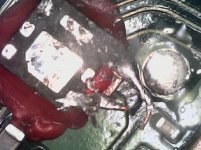
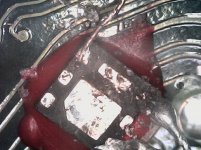
Those solder joints look fragileWell, I switched to the front and still ==*.
...but I will try switching the wire to a larger gauge before complaining too much
All points make correct continuity, this photo was taken after I reopened so I haven't tidied the thermal paste.
. Dont mind with the broken capacitor. I've seen several cases of people who still managed to glitch their consoles even after damaging the capacitor.
Last edited by Viktorsilva,

Sorry if I don't use the forum correctly, it's the first time I've posted something.
I already installed the rp2040 to my console. I have already installed before, but now I had a problem. The chip light flashed 2 long times and one short time. But I already changed the flex twice. Now place the mosfet on the back of the board but everything is the same.
Note: Already console was fine. But I left him downloading a game at night and the next morning he wouldn't enter the hack.
Note 2: I also changed the chip and everything remains the same.
Note: 3. currently I have ==*
Attachments
Can you post a better picture of mosfet solderin (from little further away) because i am not able to see good.Sorry if I don't use the forum correctly, it's the first time I've posted something.
I already installed the rp2040 to my console. I have already installed before, but now I had a problem. The chip light flashed 2 long times and one short time. But I already changed the flex twice. Now place the mosfet on the back of the board but everything is the same.
Note: Already console was fine. But I left him downloading a game at night and the next morning he wouldn't enter the hack.
Note 2: I also changed the chip and everything remains the same.
Note: 3. currently I have ==*
I dont think you are using these points:
Attachments
hey guys. Looking at this installation, I wonder if:Sorry if I don't use the forum correctly, it's the first time I've posted something.
I already installed the rp2040 to my console. I have already installed before, but now I had a problem. The chip light flashed 2 long times and one short time. But I already changed the flex twice. Now place the mosfet on the back of the board but everything is the same.
Note: Already console was fine. But I left him downloading a game at night and the next morning he wouldn't enter the hack.
Note 2: I also changed the chip and everything remains the same.
Note: 3. currently I have ==*
- if any point-to-point continuity test was carried out (very important to determine whether the magnet wire was stripped at the connection points)
-What is the console model?
- Was the removal of the CPU flex done well?
-Are these points you are using on the back of the motherboard? Can you take a photo from further away to see better?
I have never installed one of these but there are several users on these forums who use this model and say it works very well. I leave the pinout here:I tried to use an AON6414A mosfet and still get an error ==*. Does anyone have a photo of its setup?
THANKS
Glad to ear it
Sure!
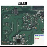
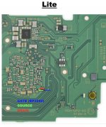
Here are some images of the Lite with a hwfly lite installed running picofly 2.73:
Here are some images of the Mariko V2 with hwfly core installed running picofly 2.73:
Glitching works quite well on both and after the first learning process, glitching usually takes less than 3 seconds. Thank you again for your hard work!
great job ! it looks very cleanSure!
Here are some images of the Lite with a hwfly lite installed running picofly 2.73:
View attachment 422096View attachment 422097View attachment 422098
Here are some images of the Mariko V2 with hwfly core installed running picofly 2.73:
View attachment 422100View attachment 422102
Glitching works quite well on both and after the first learning process, glitching usually takes less than 3 seconds. Thank you again for your hard work!
Similar threads
- Replies
- 4
- Views
- 2K
- Replies
- 2
- Views
- 558
- Replies
- 42
- Views
- 6K
Site & Scene News
New Hot Discussed
-
-
30K views
Nintendo Switch firmware update 18.0.1 has been released
A new Nintendo Switch firmware update is here. System software version 18.0.1 has been released. This update offers the typical stability features as all other... -
24K views
New static recompiler tool N64Recomp aims to seamlessly modernize N64 games
As each year passes, retro games become harder and harder to play, as the physical media begins to fall apart and becomes more difficult and expensive to obtain. The... -
23K views
Nintendo officially confirms Switch successor console, announces Nintendo Direct for next month
While rumors had been floating about rampantly as to the future plans of Nintendo, the President of the company, Shuntaro Furukawa, made a brief statement confirming... -
22K views
TheFloW releases new PPPwn kernel exploit for PS4, works on firmware 11.00
TheFlow has done it again--a new kernel exploit has been released for PlayStation 4 consoles. This latest exploit is called PPPwn, and works on PlayStation 4 systems... -
20K views
Nintendo takes down Gmod content from Steam's Workshop
Nintendo might just as well be a law firm more than a videogame company at this point in time, since they have yet again issued their now almost trademarked usual...by ShadowOne333 129 -
17K views
Name the Switch successor: what should Nintendo call its new console?
Nintendo has officially announced that a successor to the beloved Switch console is on the horizon. As we eagerly anticipate what innovations this new device will... -
16K views
A prototype of the original "The Legend of Zelda" for NES has been found and preserved
Another video game prototype has been found and preserved, and this time, it's none other than the game that spawned an entire franchise beloved by many, the very...by ShadowOne333 32 -
15K views
Anbernic reveals specs details of pocket-sized RG28XX retro handheld
Anbernic is back with yet another retro handheld device. The upcoming RG28XX is another console sporting the quad-core H700 chip of the company's recent RG35XX 2024... -
13K views
DOOM has been ported to the retro game console in Persona 5 Royal
DOOM is well-known for being ported to basically every device with some kind of input, and that list now includes the old retro game console in Persona 5 Royal... -
12K views
Nintendo Switch Online adds two more Nintendo 64 titles to its classic library
Two classic titles join the Nintendo Switch Online Expansion Pack game lineup. Available starting April 24th will be the motorcycle racing game Extreme G and another...
-
-
-
272 replies
Name the Switch successor: what should Nintendo call its new console?
Nintendo has officially announced that a successor to the beloved Switch console is on the horizon. As we eagerly anticipate what innovations this new device will...by Costello -
232 replies
Nintendo officially confirms Switch successor console, announces Nintendo Direct for next month
While rumors had been floating about rampantly as to the future plans of Nintendo, the President of the company, Shuntaro Furukawa, made a brief statement confirming...by Chary -
129 replies
Nintendo takes down Gmod content from Steam's Workshop
Nintendo might just as well be a law firm more than a videogame company at this point in time, since they have yet again issued their now almost trademarked usual...by ShadowOne333 -
124 replies
New static recompiler tool N64Recomp aims to seamlessly modernize N64 games
As each year passes, retro games become harder and harder to play, as the physical media begins to fall apart and becomes more difficult and expensive to obtain. The...by Chary -
85 replies
Ubisoft reveals 'Assassin's Creed Shadows' which is set to launch later this year
Ubisoft has today officially revealed the next installment in the Assassin's Creed franchise: Assassin's Creed Shadows. This entry is set in late Sengoku-era Japan...by Prans -
82 replies
Nintendo Switch firmware update 18.0.1 has been released
A new Nintendo Switch firmware update is here. System software version 18.0.1 has been released. This update offers the typical stability features as all other...by Chary -
81 replies
TheFloW releases new PPPwn kernel exploit for PS4, works on firmware 11.00
TheFlow has done it again--a new kernel exploit has been released for PlayStation 4 consoles. This latest exploit is called PPPwn, and works on PlayStation 4 systems...by Chary -
78 replies
"Nintendo World Championships: NES Edition", a new NES Remix-like game, launching July 18th
After rumour got out about an upcoming NES Edition release for the famed Nintendo World Championships, Nintendo has officially unveiled the new game, titled "Nintendo...by ShadowOne333 -
71 replies
DOOM has been ported to the retro game console in Persona 5 Royal
DOOM is well-known for being ported to basically every device with some kind of input, and that list now includes the old retro game console in Persona 5 Royal...by relauby -
65 replies
Microsoft is closing down several gaming studios, including Tango Gameworks and Arkane Austin
The number of layoffs and cuts in the videogame industry sadly continue to grow, with the latest huge layoffs coming from Microsoft, due to what MIcrosoft calls a...by ShadowOne333
-
Popular threads in this forum
General chit-chat
- No one is chatting at the moment.
-
-
-
-
-
-
-
-
-
-
-
-
-
-
-
-
-
-
 @
Veho:
Ah, yes, portrait mode, surely the best way to film a row of people. If only there were some way to fit a wider shot, at the expense of height... if only...+1
@
Veho:
Ah, yes, portrait mode, surely the best way to film a row of people. If only there were some way to fit a wider shot, at the expense of height... if only...+1 -
-
-
-
 @
BigOnYa:
Diddy - "I never touched her, that bitch is crazy." Video is released. Diddy - " Ok I did it, i am remorseful for my actions during my darkest times." Lol
@
BigOnYa:
Diddy - "I never touched her, that bitch is crazy." Video is released. Diddy - " Ok I did it, i am remorseful for my actions during my darkest times." Lol -
-
-